DfMA is increasingly discussed across modular, prefabricated and offsite construction, but the term is often reduced to a simple idea: “designing something so it is easier to manufacture.”
That is only part of the picture.
DfMA stands for Design for Manufacture and Assembly. In construction, it is an approach that considers how building components and systems will be manufactured, coordinated, transported and assembled while they are still being designed.
For modular construction, this is particularly important because much of the building is produced away from the final site. Wall panels, framing systems, floor cassettes, roof systems, MEP assemblies and even complete volumetric modules may need to be developed and coordinated before factory production begins.
DfMA therefore connects design decisions with the realities of modular manufacturing, prefabrication and assembly.
BIM can support that process by providing the coordinated digital information needed to develop modular systems, manage interfaces and produce shop and fabrication documentation before information reaches production.
What Does DfMA Mean?
DfMA means Design for Manufacture and Assembly.
The idea combines two related design considerations:
Design for Manufacture (DfM) considers how efficiently and consistently a component can be manufactured.
Design for Assembly (DfA) considers how those components will fit together and be assembled into a larger system.
Combined as DfMA, the design process considers both manufacturing and assembly rather than treating them as issues to solve after the design is largely complete.
For construction, this means asking questions such as:
- Can this component be manufactured using the selected building system?
- Can similar components be standardized?
- Are dimensions compatible with manufacturing constraints?
- Are openings and penetrations coordinated?
- Can the assembly be installed in the intended sequence?
- Are interfaces between components clearly defined?
- Does production have the information needed to manufacture the system?
- Can repeated components use consistent design logic?
DfMA does not mean that every component must be identical.
It means that manufacturing and assembly considerations become part of the design-development process.
What Is DfMA in Construction?
In construction, DfMA is a design approach that develops building systems with manufacturing and assembly requirements in mind before those systems reach production or installation.
Traditional building documentation may primarily communicate design intent: dimensions, materials, layouts, structural requirements and general construction information.
A DfMA-oriented workflow goes further.
It asks how that information will translate into actual components and assemblies.
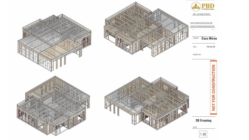
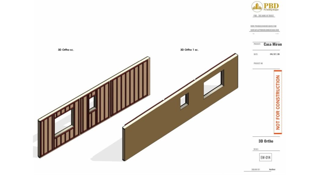
For example, a wall shown in an architectural model may eventually need to become:
- A defined wall panel
- A structural framing assembly
- A sheathing layout
- A set of openings
- A coordinated service zone
- A transportable component
- A production drawing
- A repeatable factory process
This difference becomes particularly important in modular construction, prefab construction and offsite construction, where components are manufactured in a controlled production environment before being transported and assembled elsewhere.
The earlier those manufacturing conditions are understood, the better the design information can be prepared for the next stage.
Why DfMA Matters in Modular Construction
Modular construction changes where and when many building decisions need to be resolved.
When a large proportion of the building is manufactured offsite, there is less opportunity to treat fabrication details as something that will simply be worked out later.
Manufacturers need coordinated information.
Dimensions must align.
Interfaces between assemblies need to be understood.
Structural framing has to work with openings and service penetrations.
Repeated modules or panels need consistent rules.
Production documentation must communicate what is actually being manufactured.
This is why DfMA in modular construction is closely connected to several principles.
Repeatability
Modular systems often contain repeated rooms, panels, modules or framing configurations.
DfMA encourages teams to identify where repetition can be used intentionally rather than redesigning every component independently.
Standardization
Standard dimensions, assemblies and component families can make information easier to coordinate and manage.
Standardization does not mean making every building identical. It means controlling variation where doing so supports manufacturing.
Dimensional Coordination
A small dimensional conflict inside a repeated assembly can become a repeated production problem.
DfMA places greater emphasis on checking these relationships before fabrication.
Manufacturing Constraints
Production equipment, material dimensions, framing methods, transport limitations and manufacturer-specific standards can all influence the design of modular components.
Assembly Logic
A component must not only be manufacturable. It also has to connect correctly with adjacent systems and support the intended assembly sequence.
Production Information
The model or design alone is not enough.
Production teams eventually need coordinated drawings, schedules, dimensions, member information and other documentation appropriate to the manufacturing workflow.
How BIM Supports DfMA for Modular Construction
BIM and DfMA are closely related, but they are not the same thing.
DfMA is a design and production-oriented approach.
BIM is a digital information process that can help teams implement that approach.
In a modular project, the information flow may look like this:
Design & Engineering Information
↓
Coordinated BIM
↓
Detailed Modular Systems
↓
DfMA Coordination
↓
Shop & Fabrication Documentation
↓
Production
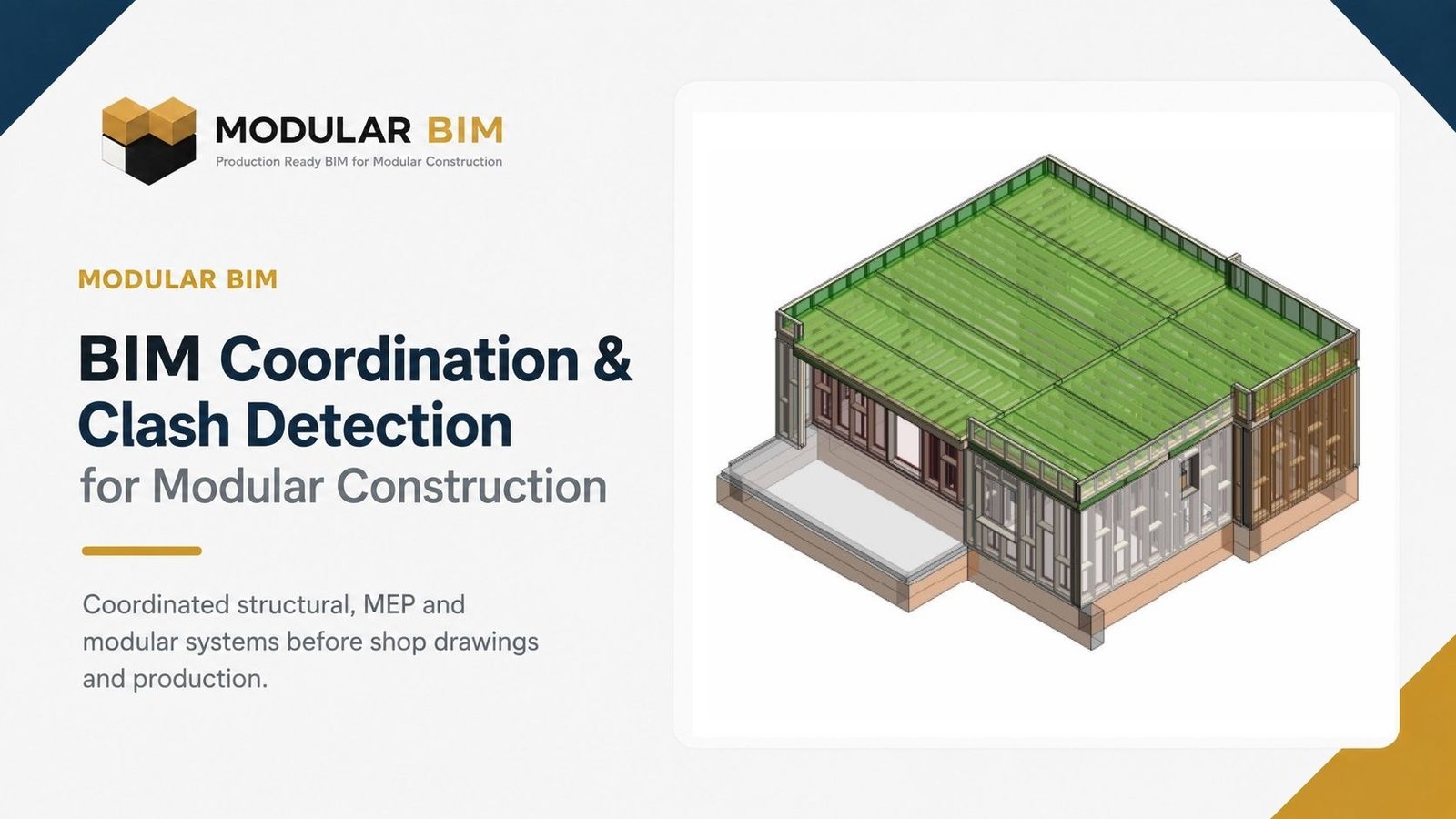
A coordinated BIM model can bring together architectural, structural, MEP and modular-system information before manufacturing documentation is developed.
That makes it possible to review relationships such as:
- Structural framing versus openings
- Wall panels versus floor systems
- Roof assemblies versus structural supports
- MEP penetrations versus studs or joists
- Module boundaries versus service routes
- Sheathing versus panel geometry
- Repeated components versus project-specific variations
- Connection and interface zones between assemblies
This is one reason BIM for modular manufacturing becomes more valuable as a project moves toward production.
The goal is not simply greater geometric detail.
The goal is better coordinated information.
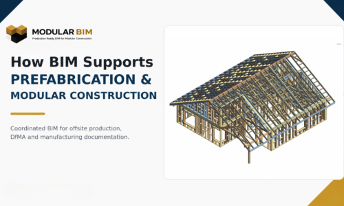
For a deeper explanation of this relationship, see our guide to BIM for prefabrication and modular construction.
Key DfMA Principles for Modular Buildings
Although DfMA strategies vary by manufacturer and construction system, several principles appear repeatedly in modular and offsite workflows.
Standardization and Repeatability
Repeated components are one of the strongest opportunities in modular construction.
A wall-panel type, floor cassette or module configuration may occur many times throughout a project.
Using consistent design rules can simplify coordination and make documentation more predictable.
However, standardization should be purposeful.
A component should not be standardized simply because it is convenient in the model. It must still satisfy architectural, structural, building-services and manufacturer requirements.
Design for Manufacturing Constraints
Every manufacturing environment has limits.
These may relate to:
- Material dimensions
- Framing methods
- Equipment
- Panel sizes
- Module sizes
- Transport dimensions
- Handling requirements
- Production sequence
- Available components
A DfMA workflow considers those constraints while systems are being developed.
For BIM teams, this means manufacturer requirements need to be understood before developing production-level assemblies.
Design for Efficient Assembly
Manufacturing a component successfully does not guarantee that it can be assembled successfully.
DfMA also considers how different systems meet.
Examples include:
- Wall-to-floor interfaces
- Wall-to-roof interfaces
- Module-to-module conditions
- Structural connection zones
- Service connections
- Openings
- Tolerances
- Installation access
The interface between systems is often where coordination becomes most important.
Coordination Before Production
Changes made while information is still digital are generally easier to manage than changes discovered after components have already entered manufacturing.
For this reason, DfMA workflows place significant value on early BIM coordination, clash detection and dimensional coordination.
Not every issue is a physical clash.
A model may be geometrically clash-free while still containing:
- Poor assembly access
- Inconsistent dimensions
- Uncoordinated openings
- Conflicting panel logic
- Missing production information
- Different assumptions between disciplines
DfMA therefore requires more than running automated clash detection.
It requires coordinated thinking around how the system will actually be manufactured and assembled.
Component and Module Optimization
A modular project contains several levels of information:
Building
↓
Modules
↓
Panels / Cassettes / Assemblies
↓
Framing and components
↓
Production information
DfMA looks at how these levels relate to each other.
Changes to a module can affect panels.
Changes to panels can affect framing.
Changes to framing can affect services.
Changes to services can affect penetrations.
This is why modular coordination needs to be approached as a system rather than as a collection of independent models.
Clear Production Information
A detailed BIM model becomes much more useful when the required information can be translated into clear production documentation.
Depending on the manufacturer and project scope, this may include:
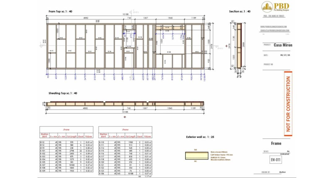
- Framing layouts
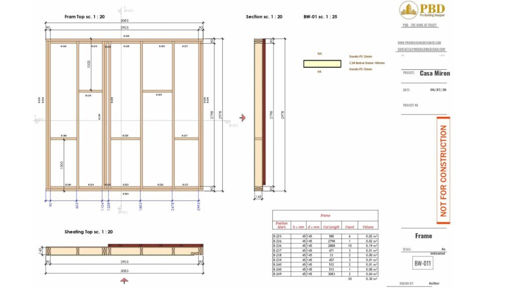
- Wall panel drawings
- Floor cassette drawings
- Roof cassette drawings
- Sections
- Details
- Member schedules
- Sheathing layouts
- Cut information
- Assembly identification
- Fabrication information
The specific output should always match the manufacturer’s agreed requirements.
DfMA Across Modular Building Systems

DfMA is not limited to volumetric modules.
The same principles can be applied across several offsite building systems.
Timber Framing
Timber framing can be developed around repeatable stud layouts, openings, headers, joists, beams and other framing components.
BIM can help coordinate these elements with architectural geometry and production documentation.
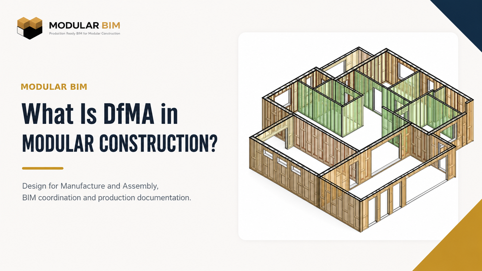
Wall Panels
Panelized wall systems are a natural application of DfMA.
Each wall can be considered as a manufactured assembly rather than simply as a line or generic wall object in the architectural model.
Panel development may consider:
- Dimensions
- Framing
- Openings
- Sheathing
- Service zones
- Interface conditions
Floor Cassettes
Floor cassettes can include coordinated joists, rim members, trimming members, openings and service penetrations.
The relationship between floor geometry and wall or module geometry is particularly important.
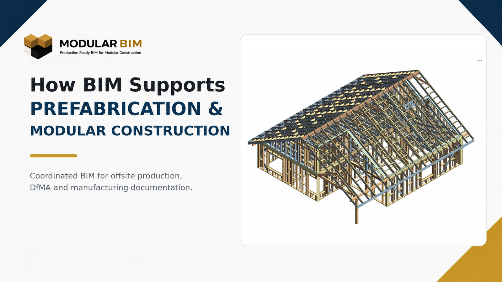
Roof Cassettes
Roof framing can similarly be developed into repeatable assemblies that coordinate structural geometry, openings, interfaces and documentation.
Light Gauge Steel Framing
DfMA principles also apply to light gauge steel systems.
Studs, tracks, headers, floor members and panel configurations can be coordinated around manufacturing and assembly requirements.
MEP Systems
Mechanical, electrical and plumbing systems can significantly affect modular production.
Penetrations, service zones and equipment positions should be coordinated with structural and architectural systems before they create conflicts in manufactured assemblies.
DfMA and Shop/Fabrication Drawings
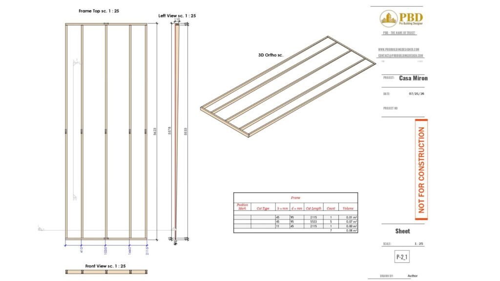
DfMA becomes commercially meaningful when coordinated design information can be turned into information that supports production.
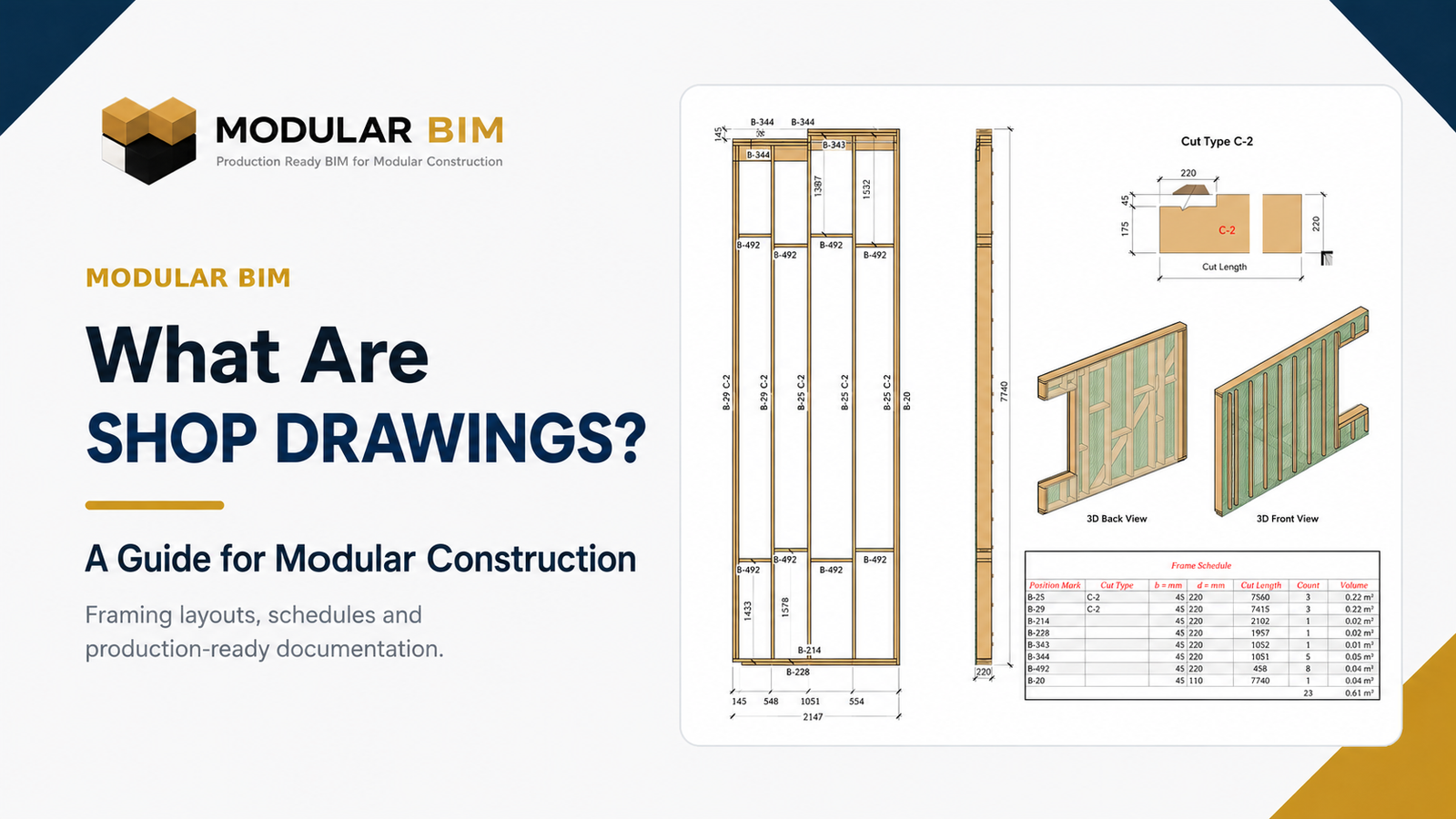
A BIM model may contain the geometry and data required to develop:
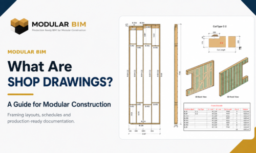
- Wall panel shop drawings
- Framing plans
- Floor cassette drawings
- Roof cassette drawings
- Fabrication drawings
- Sections and details
- Member schedules
- Assembly information
- Production drawings
This relationship can be summarized as:
Engineering Intent
↓
Coordinated BIM
↓
Manufacturable Assemblies
↓
Shop / Fabrication Drawings
↓
Production Documentation
A good DfMA workflow does not treat shop drawings as an unrelated task performed after BIM coordination.
Where the project workflow allows it, the documentation should be developed from the same coordinated information environment.
Learn more about our modular BIM services for production modeling, coordination and documentation.
Example DfMA Workflow for a Modular Project
A practical modular DfMA workflow may follow seven stages.
1. Design & Engineering Information
Architectural, structural and building-services information establishes the design requirements.
2. Modular BIM Development
The building information is developed into coordinated modules, framing systems, panels or other modular assemblies.
3. Structural and MEP Coordination
Framing, services, openings and penetrations are reviewed against the modular system.
4. Component and Assembly Development
Individual walls, panels, floors, roofs or modules are developed to the level required for the project.
5. Coordination and Manufacturability Review
The system is reviewed against available manufacturer requirements, interfaces, dimensions and agreed production constraints.
6. Shop & Production Documentation
Coordinated assemblies are translated into the required drawings, schedules and production information.
7. Manufacturer Review and Production
The manufacturer reviews the information according to its own production workflow before approved information moves into manufacturing.
This final stage is important.
BIM and DfMA support manufacturing decisions; they do not replace the manufacturer’s own review, engineering responsibilities or production controls.
What Are the Benefits of DfMA in Modular Construction?
The value of DfMA is not that it magically removes every project problem.
Its value comes from shifting more attention toward manufacturing and assembly while information can still be coordinated.
Potential benefits include:
Improved Coordination
Architectural, structural, MEP and modular-system requirements can be reviewed together.
Reduced Production Uncertainty
More issues can be identified before information reaches manufacturing.
More Repeatable Assemblies
Repeated components can follow controlled design and documentation rules.
More Consistent Documentation
Models, drawings and schedules can be developed from a coordinated information environment.
Better Design-to-Production Information Flow
Manufacturing requirements can be considered earlier instead of being introduced only after general design development.
Earlier Conflict Identification
Potential interface and dimensional problems can be found while changes are still being coordinated digitally.
Support for Efficient Assembly
Components can be developed with attention to how they connect with surrounding systems.
These benefits depend on the quality of the information, collaboration between disciplines, manufacturer requirements and the level of coordination achieved.
DfMA is a process—not an automatic guarantee of production efficiency.
DfMA vs Traditional Construction Documentation
Traditional construction documentation and DfMA documentation are not necessarily competing approaches.
They often serve different purposes.
Traditional design documentation may focus strongly on:
- Design intent
- Building geometry
- Materials
- Code information
- Engineering requirements
- Construction relationships
A DfMA-oriented modular workflow places additional emphasis on:
- Manufacturing
- Repeatability
- Componentization
- Assembly
- Interfaces
- Production constraints
- Fabrication information
- Factory documentation
The key difference is the direction of the information.
Traditional documentation asks:
“What needs to be built?”
DfMA introduces another question:
“How should this system be developed so that it can be manufactured and assembled effectively?”
For modular construction, both questions matter.
DfMA Is the Link Between Design and Modular Production
DfMA is particularly relevant to modular construction because modular buildings depend on coordinated systems that move from digital information into physical production.
The process requires more than simply developing a detailed BIM model.
Architectural information, engineering requirements, framing systems, services, panels, cassettes, interfaces and production documentation must work together.
That is where DfMA BIM becomes valuable.
BIM provides the digital environment.
DfMA provides the manufacturing and assembly mindset.
Together, they can support a more structured information path from design through modular production.
Explore our production-ready modular BIM projects to see how detailed framing, modular systems and documentation can be developed from coordinated building information.
Frequently Asked Questions
What does DfMA stand for?
DfMA stands for Design for Manufacture and Assembly. It is an approach that considers how components will be manufactured and how they will later be assembled while the design is being developed.
What is DfMA in construction?
DfMA in construction means developing building systems with manufacturing, prefabrication and assembly requirements in mind. It is particularly relevant to modular and offsite construction, where components may be produced in a factory before reaching the site.
How is DfMA used in modular construction?
DfMA can be used to develop repeatable modules, wall panels, framing systems, floor cassettes, roof systems and other prefabricated components while considering manufacturing constraints, dimensional coordination, interfaces and assembly requirements.
How does BIM support DfMA?
BIM supports DfMA by providing a coordinated digital environment where architectural, structural, MEP and modular-system information can be developed and reviewed before shop drawings and production documentation are created.
What is the difference between DfM and DfMA?
DfM, or Design for Manufacture, focuses primarily on how a component can be manufactured.
DfMA considers both manufacturing and the way components will later be assembled into larger systems.
What are the main DfMA principles?
Common DfMA principles include standardization, repeatability, manufacturing-aware design, efficient assembly, early coordination, controlled interfaces and clear production information.
Need BIM Support for a Modular Project?
Modular BIM supports modular manufacturers and offsite construction teams with coordinated BIM models, modular systems, framing documentation, shop drawings, production documentation and DfMA-oriented BIM workflows.
We help develop the information between design and modular production.
Explore our modular BIM services or view our production-ready modular BIM projects.
Related Posts