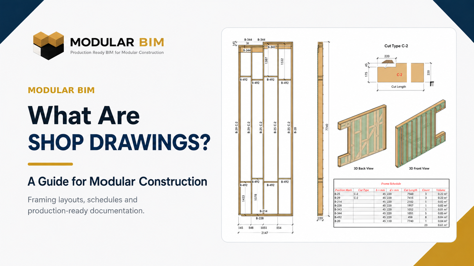
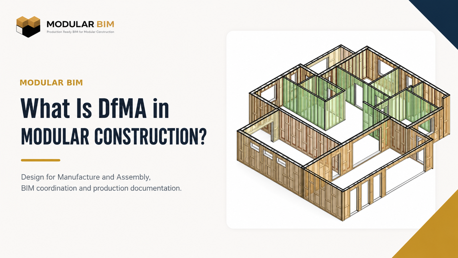
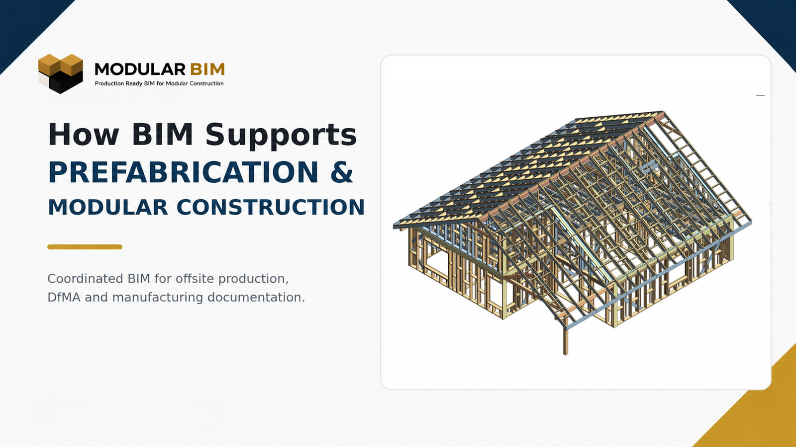
Shop drawings are detailed technical drawings used to communicate how specific building components, assemblies or systems are to be fabricated, coordinated or assembled. In modular construction, shop drawings can translate coordinated BIM information into production-oriented documentation for timber framing, wall panels, floor and roof cassettes, light-gauge steel systems and other prefabricated components.
They sit much closer to the actual component or assembly than a general building drawing.
That distinction becomes especially important in modular and offsite construction, where a large part of the building may be manufactured before it reaches the site.
A drawing that is sufficient to communicate overall design intent may not contain enough information for a production team to understand how a specific wall panel, framing assembly or cassette needs to be developed.
This is where shop drawings become an important part of the information flow between design, coordination and production.
What Are Shop Drawings?
A shop drawing is a detailed drawing prepared for a specific building component, system or assembly.
Unlike drawings that primarily communicate the overall architectural or engineering intent of a building, shop drawings usually focus more closely on the information required to coordinate, fabricate, assemble or install a particular element.
Depending on the project and discipline, a shop drawing may show information such as:
- Component dimensions
- Member sizes
- Member identification
- Material information
- Openings
- Assembly geometry
- Sections and details
- Connection or interface information where applicable
- Panel or component identification
- Schedules
- References to related drawings or coordinated models
Not every shop drawing contains all of these items.
The required content depends on the component, project stage, contractual responsibilities, manufacturer requirements and intended use of the drawing.
For modular construction, shop drawings often become particularly important because building systems are being converted from general design information into defined components that may be produced in a factory or offsite environment.
What Are Shop Drawings Used for in Construction?
In construction, shop drawings help communicate information about specific systems or components in more detail than the overall design documents typically provide.
A simplified information progression might look like this:
Design Intent
↓
Detailed Component Information
↓
Coordination
↓
Fabrication / Assembly Information
The purpose is not simply to redraw the architect’s or engineer’s drawings at a larger scale.
A useful shop drawing should communicate the information required for the specific component being developed.
For example, an architectural wall may establish:
- Wall location
- Overall thickness
- Openings
- Materials
- Design intent
A detailed timber wall-panel shop drawing may need to go further and communicate:
- Overall panel dimensions
- Stud layout
- Headers
- Sills
- Openings
- Framing around doors and windows
- Sheathing
- Component marks
- Sections
- Member information
That additional level of information is what moves the documentation closer to fabrication or production.
Shop Drawings vs Construction Drawings
Shop drawings and construction drawings serve related but different purposes.
| Construction Drawings | Shop Drawings |
|---|---|
| Communicate broader building design and construction intent | Communicate detailed information for specific components or assemblies |
| Cover multiple building systems | Usually focus on a defined system, component or trade |
| Establish dimensions, materials and design requirements | Develop component-level dimensions, layouts and assembly information |
| Used broadly across construction | Often closer to fabrication, manufacturing or installation |
| Typically prepared as part of the design documentation | Often developed from approved design/engineering information for a specific system |
The distinction is not always identical on every project.
Different contracts, jurisdictions, disciplines and manufacturers may use the term shop drawing differently.
The important point is that construction drawings generally establish what the overall building should be, while shop drawings provide more detailed information about how particular components or systems are developed.
In modular construction, this distinction can become even stronger because production teams may need information organized around individual modules, panels, frames or cassettes.
Shop Drawings vs Fabrication Drawings
The terms shop drawings and fabrication drawings are sometimes used interchangeably, but they do not always mean exactly the same thing.
A shop drawing may communicate detailed component or assembly information needed for coordination, review, fabrication or installation.
A fabrication drawing is generally more directly focused on the information required to manufacture a specific component.
Depending on the system, fabrication drawings may include:
- Exact component geometry
- Member dimensions
- Cut information
- Hole or opening locations
- Material specifications
- Part identification
- Assembly information
- Fabrication details
- Quantities or schedules where required
In some workflows, a shop drawing becomes the fabrication drawing.
In others, the shop drawing may sit one step earlier and be used for coordination or approval before manufacturer-specific fabrication information is generated.
That is why the terminology should always be understood in the context of the project.
For modular construction, the important relationship is:
Coordinated Design Information
↓
Detailed Shop Information
↓
Fabrication Information
↓
Production
Shop Drawings vs Production Drawings
Production drawings are another closely related category.
In traditional site-based construction, the emphasis may be on communicating how an element should be installed at the project location.
Modular and offsite construction introduces another environment:
the factory.
Production teams may need documentation organized around:
- Individual panels
- Modules
- Framing assemblies
- Floor cassettes
- Roof cassettes
- Repeated component types
- Manufacturing sequence
- Component identification
- Material and member schedules
A production drawing is therefore often structured around what a manufacturing team needs to build or assemble.
The exact difference between a shop drawing and a production drawing varies from company to company.
Some modular manufacturers use the terms almost interchangeably.
Others maintain separate drawing stages for:
coordination → shop drawing → fabrication → production
The naming is less important than ensuring that the information is appropriate for its intended use.
Why Shop Drawings Matter in Modular Construction
Shop drawings become especially important in modular construction because many building components are developed as repeatable manufactured systems rather than being assembled entirely on site.
Consider a conventional wall.
Some site adjustments may still be possible while framing or installation is taking place.
Now consider a panelized modular wall manufactured in a controlled factory environment.
That wall may need to arrive at production with its:
- Dimensions coordinated
- Openings resolved
- Framing defined
- Interfaces understood
- Sheathing coordinated
- Services accounted for
- Component identification established
If the same panel type occurs repeatedly, an unresolved issue may affect multiple components rather than a single location.
This creates a stronger need for accurate and coordinated production information.
Repeatability
Modular buildings often use repeated assemblies.
Shop drawings provide a way to define those assemblies consistently while controlling project-specific variations.
Dimensional Coordination
Panel, module and cassette dimensions need to relate accurately to adjacent systems.
A small dimensional problem can become a larger issue when repeated across multiple assemblies.
Interfaces
Modular systems contain many important interfaces:
- Wall to floor
- Wall to roof
- Panel to panel
- Module to module
- Structure to MEP
- Opening to framing
- Sheathing to assembly boundaries
Shop drawings can make these relationships easier to understand and review.
Coordination Before Production
Once manufacturing begins, changes may affect materials, repeated components, schedules and other downstream information.
Detailed coordination before information reaches production can therefore reduce uncertainty.
This does not mean that shop drawings automatically eliminate errors.
They remain dependent on accurate source information, engineering, coordination, QA/QC and manufacturer review.
How BIM Supports Modular Shop Drawings
BIM can provide the coordinated digital environment from which detailed modular systems and shop drawings are developed.
A typical workflow might look like this:
Design & Engineering Information
↓
Coordinated BIM
↓
Detailed Modular Systems
↓
Shop & Fabrication Drawings
↓
Production Documentation
↓
Manufacturing
The value of BIM in this workflow is not simply the ability to view the building in 3D.
A coordinated model can connect information across:
- Architecture
- Structural framing
- MEP systems
- Wall assemblies
- Floor systems
- Roof systems
- Openings
- Panels
- Modules
- Member schedules
When those systems are developed within a coordinated information environment, the resulting drawings can maintain a clearer relationship with the model.
For example, if a wall opening changes, that change may affect:
architectural geometry → wall framing → sheathing → panel documentation → related schedules
A BIM-based workflow can make these dependencies easier to manage than maintaining completely disconnected models and drawings.
For more on the wider process, read our guide to BIM for prefabrication and modular construction.
Types of Shop Drawings Used in Modular Construction
Different modular building systems require different types of documentation.
Timber Framing Shop Drawings
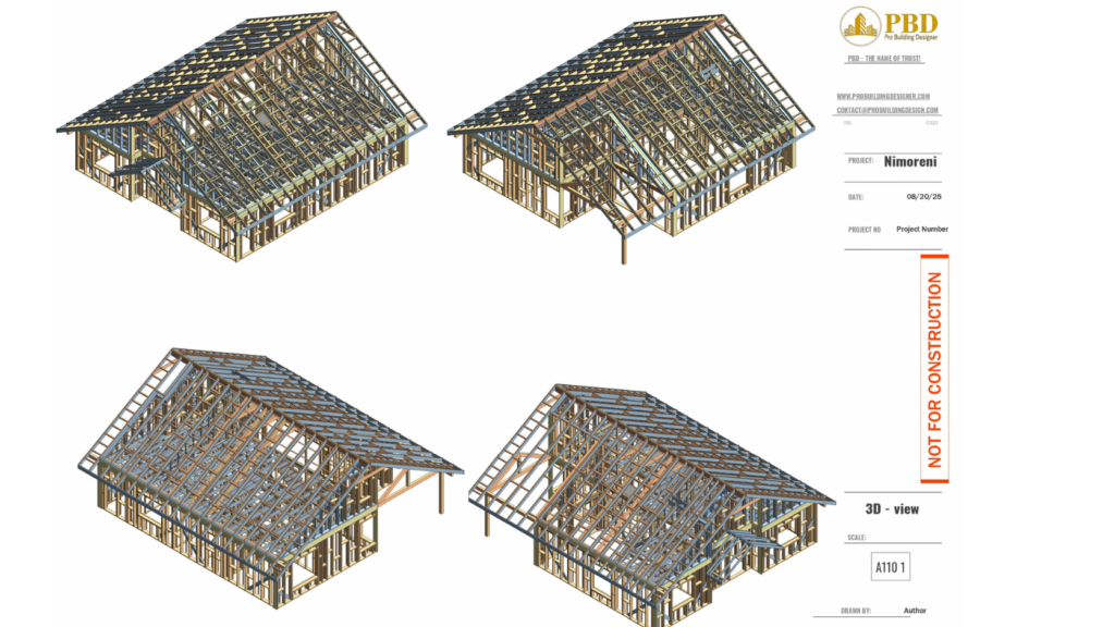
Timber framing shop drawings can communicate detailed information for structural wall, floor and roof framing.
Depending on the project scope, they may include:
- Studs
- Plates
- Beams
- Headers
- Sills
- Joists
- Rafters
- Blocking
- Member marks
- Dimensions
- Sections
- Schedules
The drawing should reflect the engineering and manufacturer information available for the project rather than inventing structural requirements.
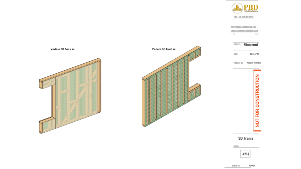
Wall Panel Shop Drawings
Panelized construction often requires individual walls to be developed as defined assemblies.
A wall-panel drawing may communicate:
- Panel dimensions
- Stud layouts
- Window and door openings
- Framing around openings
- Sheathing
- Panel identification
- Assembly build-up
- Sections
- Interface conditions
Panel documentation is particularly useful where multiple wall assemblies share common production logic.
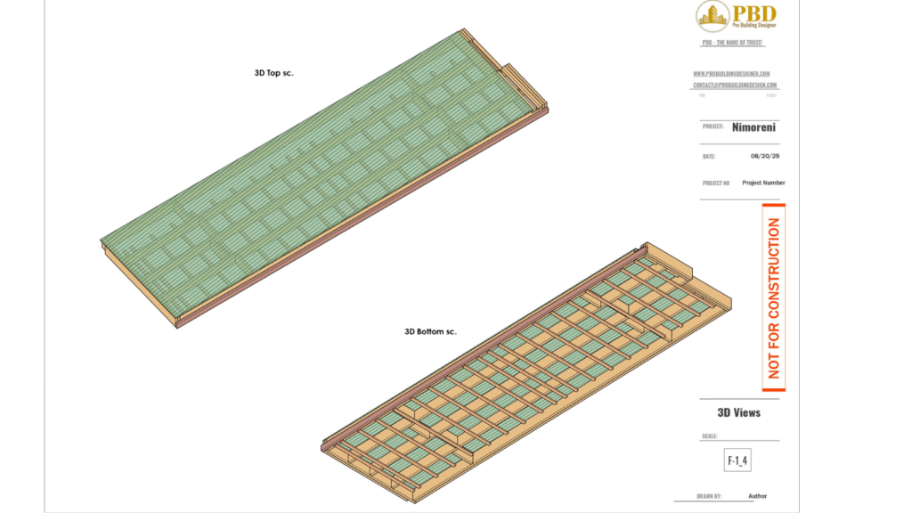
Floor Cassette Drawings
Floor cassettes may include:
- Joist layouts
- Rim members
- Trimmers
- Openings
- Structural members
- Sheathing
- Component identification
- Dimensions
- Sections
- Member schedules
MEP openings and penetrations may also need to be coordinated with the structural floor system before production.
Roof Cassette Drawings
Roof systems can similarly be developed into coordinated assemblies.
Depending on the construction method, roof documentation may include:
- Rafters or joists
- Beams
- Trimmers
- Openings
- Sheathing
- Assembly boundaries
- Sections
- Member schedules
A coordinated roof cassette should also relate correctly to the walls, supports and adjacent assemblies below it.
LGS Framing Shop Drawings
Light-gauge steel systems may require documentation for:
- Studs
- Tracks
- Headers
- Bracing
- Openings
- Panel layouts
- Floor framing
- Roof framing
- Connection/interface zones
As with timber systems, the level of production detail depends on the manufacturer’s requirements and the engineering information provided.
MEP Fabrication and Coordination Drawings
Mechanical, electrical and plumbing systems can be critical in modular manufacturing because services often pass through confined structural and assembly zones.
MEP-related drawings may support the coordination of:
- Ductwork
- Pipework
- Electrical containment
- Equipment
- Penetrations
- Service zones
- Connection locations
The objective is to identify and coordinate these relationships before they interfere with framing, panels or other manufactured systems.
What Information Is Included in a Shop Drawing?
There is no universal checklist that applies to every shop drawing.
The required information depends on the component and project.
However, modular shop drawings may include some combination of the following.
Dimensions
Dimensions define the geometry and location of components, openings and assembly boundaries.
Member Sizes
Structural framing drawings may identify member depths, widths or profiles based on the engineering information supplied for the project.
Member Identification
Individual framing elements may receive position marks or IDs that correspond with schedules or production information.
Panel or Assembly IDs
Panels, cassettes and other prefabricated assemblies may need unique identifiers.
Openings
Doors, windows, service openings and penetrations need to be coordinated with the surrounding assembly.
Sections and Details
Sections can clarify conditions that are difficult to understand in elevation or plan alone.
Material Information
Drawings may identify sheathing, framing materials or other assembly components where required.
Schedules
Member or component schedules can help organize repetitive information such as:
- Position marks
- Sizes
- Lengths
- Counts
- Material types
Interface Information
Where appropriate, the drawing may communicate how one assembly relates to another.
The exact information should always be matched to the manufacturer’s workflow rather than adding unnecessary detail simply because BIM makes it possible.
Example: Timber Modular Shop Drawing Workflow
A timber modular project provides a useful example of how shop drawings can develop from coordinated building information.
The process might begin with:
Architectural Information
Structural Engineering Information
↓
1. Coordinated Timber BIM
The building geometry, levels, openings and primary structural requirements are established within the model.
↓
2. Timber Framing Development
Walls, floors and roof systems are developed into detailed framing assemblies based on the available engineering and project requirements.
↓
3. Wall and Cassette Development
Individual wall panels, floor cassettes and roof assemblies are identified and coordinated.
↓
4. Coordination
Openings, interfaces, structural members and relevant service requirements are reviewed.
↓
5. Shop Drawings
The coordinated assemblies are translated into detailed drawings showing the information required for the project.
↓
6. Member Schedules and Production Information
Framing information can be organized into schedules containing member identification, dimensions, lengths and quantities where required.
↓
7. Production Documentation
The final documentation package is structured to match the agreed manufacturer and project requirements.
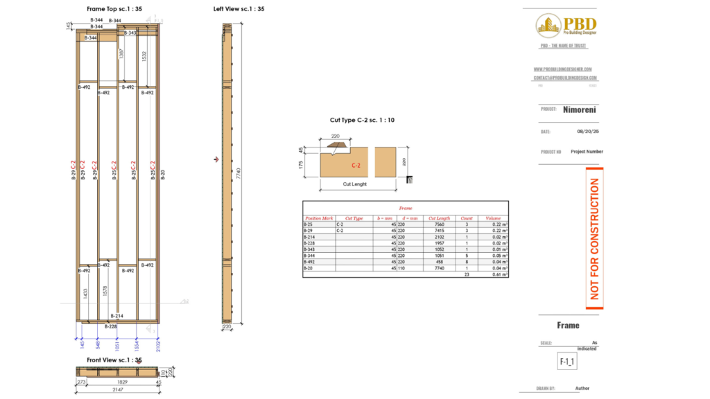
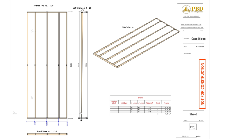
A real project drawing might therefore combine:
- Frame elevation
- Plan or top view
- Section
- 3D assembly view
- Member position marks
- Member schedule
- Assembly build-up
This is very different from simply exporting a screenshot from a BIM model.
The purpose is to communicate structured information.
Explore our production-ready modular BIM projects to see examples of coordinated framing and documentation workflows.
How Shop Drawings Support DfMA
Shop drawings are closely connected to Design for Manufacture and Assembly (DfMA) because both focus attention on how components move from design into manufacturing and assembly.
DfMA asks questions such as:
- Can this component be manufactured efficiently?
- Can it be standardized?
- Can it be repeated?
- Are interfaces coordinated?
- Can it be assembled as intended?
- Do manufacturing constraints influence the design?
Shop drawings help communicate the detailed information produced by those decisions.
For example, a standardized wall assembly becomes much more useful when production can identify:
- Its dimensions
- Framing
- Openings
- Component marks
- Materials
- Interface conditions
Similarly, a floor cassette designed around repeated framing principles requires clear documentation before it becomes a useful production system.
This creates a relationship between:
DfMA Principles
↓
Coordinated BIM
↓
Manufacturable Components
↓
Shop / Fabrication Drawings
↓
Production
Read our practical guide to DfMA in modular construction for a deeper explanation of the manufacturing and assembly principles behind this workflow.
Shop Drawings Are Part of the Design-to-Production Information Flow
For modular and offsite manufacturers, shop drawings should not be viewed simply as another drawing deliverable.
Their value comes from their position within a larger information workflow.
Design information establishes what the building needs to achieve.
BIM coordination brings multiple systems together.
Detailed modular modeling develops the assemblies.
Shop and fabrication drawings communicate those assemblies.
Production documentation prepares the information for the manufacturing workflow.
This is why a detailed BIM model alone is not necessarily production-ready.
A model may contain a great deal of geometry while still lacking the organization, coordination or documentation required by production.
The objective should be a controlled flow of information:
Design → Coordination → Detailed Systems → Documentation → Production
That is the role shop drawings can play within modular construction.
Frequently Asked Questions
What are shop drawings?
Shop drawings are detailed technical drawings used to communicate information about specific building components, assemblies or systems. They may include dimensions, member information, materials, sections, schedules and other information required for coordination, fabrication, assembly or installation.
What is the purpose of a shop drawing?
The purpose of a shop drawing is to provide more detailed information about a particular component or system than is typically shown in the general construction documents. In modular construction, shop drawings can help translate coordinated design information into production-oriented documentation.
Who uses shop drawings?
Shop drawings may be used by manufacturers, fabricators, contractors, installers, engineers, architects, coordinators and other project stakeholders depending on the system and contractual workflow.
What is the difference between shop drawings and construction drawings?
Construction drawings generally communicate the broader design and construction requirements of a building. Shop drawings typically focus more closely on the detailed information for a specific component, assembly or system.
What is the difference between shop drawings and fabrication drawings?
The terms sometimes overlap. Shop drawings may be used for detailed coordination, review, fabrication or installation, while fabrication drawings tend to focus more directly on manufacturing information for individual components. The exact terminology varies between projects and manufacturers.
Are shop drawings required for modular construction?
The documentation requirements depend on the manufacturer, project, system, contract and jurisdiction. Modular construction commonly requires detailed component and production information, but the exact drawing types and approval procedures should be defined for each project.
How does BIM help create shop drawings?
BIM can provide a coordinated digital environment in which architecture, structure, MEP and modular systems are developed together. Detailed shop drawings can then be produced from coordinated model information while maintaining relationships between models, drawings and schedules.
Need Shop Drawing Support for a Modular Project?
Modular BIM supports modular manufacturers and offsite construction teams with coordinated BIM models, timber and LGS framing, wall panels, floor and roof cassettes, shop drawings, fabrication-oriented documentation and production BIM workflows.
Our focus is helping develop the information between design and modular production.
Explore our modular BIM services or view our production-ready modular BIM projects.
Related Posts