By Faisal Khan | Modular BIM | Founder & CEO, Pro Building Designer
Timber framing is well suited to modular and panelized construction because walls, floors, roofs and other assemblies can be developed as repeatable building systems before they reach the construction site.
But a detailed timber model alone does not make a project ready for offsite production.
For modular manufacturers, the information behind the geometry matters just as much as the geometry itself.
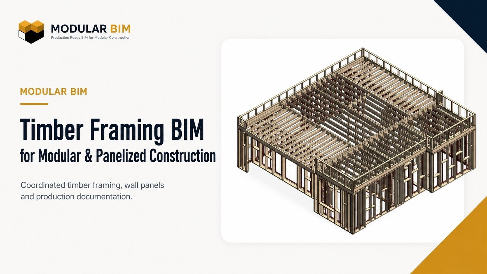
Timber framing BIM combines coordinated building geometry with structural members, openings, wall panels, floor and roof assemblies, schedules and production documentation so that timber systems can be developed within a connected digital workflow.
Used properly, BIM can help move a project from architectural and engineering information toward coordinated framing systems, panelized assemblies, shop drawings and manufacturing documentation.
That makes timber framing BIM particularly valuable for modular construction, panelized construction and other offsite timber systems.
What Is Timber Framing BIM?
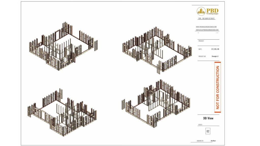
Timber framing BIM is the use of Building Information Modeling to develop and coordinate timber structural systems as information-rich building assemblies rather than disconnected 2D framing drawings.
A timber BIM model may contain:
- Studs
- Plates
- Headers
- Beams
- Joists
- Rafters
- Blocking
- Openings
- Sheathing
- Wall assemblies
- Floor assemblies
- Roof assemblies
- Panel boundaries
- Member identification
- Schedules
The important distinction is that BIM allows these components to exist within the wider building context.
A wall panel is not simply a standalone elevation.
It relates to:
Architecture → Structure → Openings → Floors → Roofs → MEP → Adjacent Panels → Production Documentation
That relationship becomes increasingly important as the project moves toward modular manufacturing.
A production-oriented timber BIM workflow therefore goes beyond creating a visually detailed wood-framing model.
It should help coordinate:
geometry + members + assemblies + interfaces + documentation
How BIM Is Used in Modular Timber Construction
A timber modular project often begins with architectural and engineering information rather than production-ready framing.
BIM can provide the environment in which that information is progressively developed.
A typical workflow may look like this:
Architectural & Engineering Information
↓
Timber Structural BIM
↓
Detailed Framing Systems
↓
Panelization & Cassette Development
↓
BIM Coordination
↓
Shop / Production Drawings
↓
Manufacturer Review
↓
Production
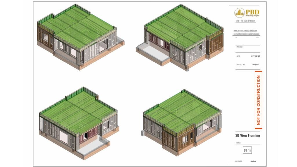
At the early stages, the model establishes the overall building geometry, levels, openings and structural requirements.
As development continues, generic walls and floors can become more specific timber systems.
Individual studs, joists, beams, headers and framing zones can then be coordinated with:
- Doors and windows
- Structural openings
- Floor systems
- Roof systems
- MEP penetrations
- Adjacent assemblies
- Module or panel boundaries
Once these relationships have been sufficiently resolved, the same coordinated information can support more detailed documentation.
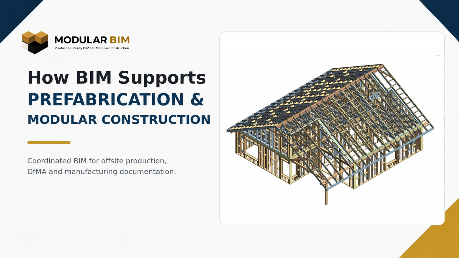
This connection between digital modeling and manufacturing is explored further in our guide to BIM for prefabrication and modular construction.
Timber Framing BIM vs Traditional Framing Drawings
Traditional framing drawings remain an important part of construction documentation.
They may communicate:
- Wall locations
- Beam positions
- Joist directions
- Member sizes
- Structural requirements
- Openings
- Sections and details
A BIM-based timber workflow does not automatically replace these documents or the engineering behind them.
Instead, BIM adds another level of coordination.
A detailed timber model can connect individual framing systems within the overall building.
For example, moving an opening may affect:
Architectural Opening
↓
Stud Layout
↓
Header Arrangement
↓
Sheathing
↓
Panel Drawing
↓
Member Schedule
That relationship is more difficult to manage when each piece of information exists independently.
In BIM, these systems can be developed from a common information environment.
This makes timber framing BIM particularly useful where projects contain:
- Repeated wall types
- Prefabricated panels
- Multiple floor assemblies
- Roof cassettes
- Modular units
- Large quantities of framing information
- Production drawings and schedules
The value is therefore not simply 3D instead of 2D.
The value is connected information.
BIM for Panelized Construction
Panelized construction is one of the strongest applications of timber framing BIM.
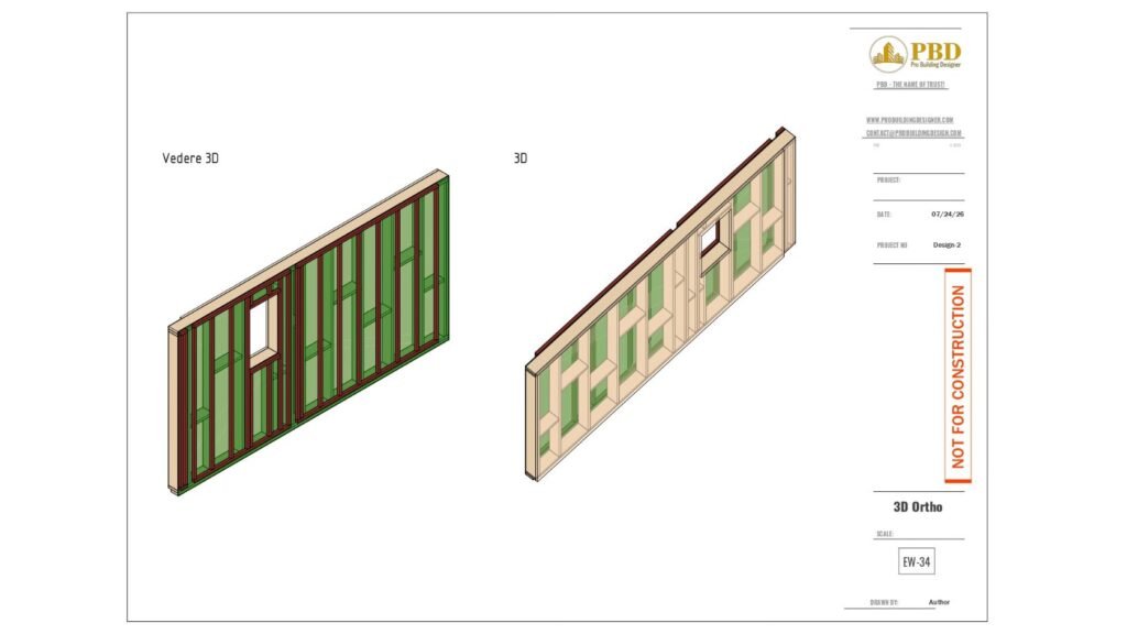
Instead of treating a building wall as one continuous site-built element, the wall system can be divided into defined panels that can be manufactured, transported and assembled.
A panelized BIM workflow may consider:
- Panel boundaries
- Overall dimensions
- Stud spacing
- Plates
- Headers
- Openings
- Sheathing
- Service zones
- Adjacent panels
- Panel identification
- Assembly information
- Production documentation
This changes how the wall is understood.
The question is no longer simply:
Where is the wall?
It becomes:
How should this wall be divided, framed, coordinated and documented as a manufactured assembly?
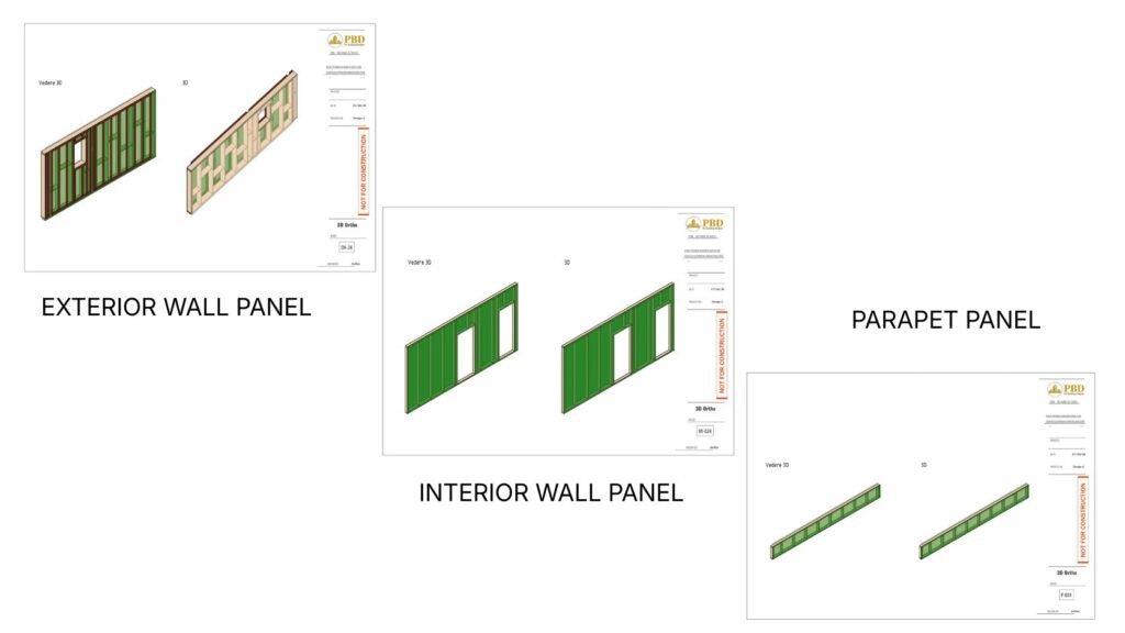
Exterior Wall Panels
Exterior timber panels may include several coordinated layers.
Depending on the project, these can include:
- Structural framing
- Exterior sheathing
- Insulation
- Membranes
- Service battens
- Interior boards
- Exterior finishes
- Doors and windows
The framing around openings must relate correctly to both architecture and structural requirements.
Panel boundaries should also be considered carefully.
A window or door located near a panel joint, for example, may create a very different framing condition than the same opening located in the middle of a panel.
BIM allows these relationships to be reviewed before production drawings are issued.
Interior Wall Panels
Interior wall systems may appear simpler, but they still require controlled information.
An interior wall panel may contain:
- Studs
- Plates
- Door openings
- Blocking
- Sheathing or boards
- Service zones
- Panel identification
Repeated internal layouts can also provide opportunities for standardization.
However, repetition should reflect actual design and manufacturing requirements rather than being imposed simply to simplify the model.
Parapet Panels
Parapets and other shorter wall assemblies can also be developed as panelized systems.
Although geometrically smaller, they still need to coordinate with:
- Roof systems
- Structural framing
- Sheathing
- Finishes
- Adjacent wall panels
- Drainage or service requirements where applicable
Treating these assemblies as defined BIM components makes it easier to connect their geometry with drawings and schedules.
Floor and Roof Cassettes in Timber BIM
Panelized timber construction is not limited to walls.
Floors and roofs can also be developed as prefabricated cassettes.
A cassette is a framed assembly that can be developed as a defined unit rather than being treated only as a collection of individual members.
This makes floor and roof cassettes an important part of the modular BIM information structure.
Floor Cassette BIM and Drawings
A floor cassette BIM model may include:
- Joists
- Rim members
- Beams
- Trimmers
- Blocking
- Structural openings
- Sheathing
- Service penetrations
- Cassette boundaries
- Dimensions
- Member identification
One of the most important coordination issues is the relationship between floor framing and building services.
A pipe or duct opening that appears straightforward on an architectural plan may conflict with:
- A joist
- A beam
- A cassette edge
- A trimmer
- Another service
Those conditions are easier to evaluate before fabrication when framing and services can be reviewed together.
Floor cassette drawings may then communicate the agreed geometry through:
- Framing layouts
- Elevations
- Sections
- Member schedules
- Dimensions
- Assembly information
Roof Cassette BIM and Drawings
Roof systems follow a similar principle.
A timber roof cassette may include:
- Rafters or roof joists
- Beams
- Trimmers
- Openings
- Sheathing
- Cassette boundaries
- Supporting wall conditions
- Member identification
Roof BIM becomes particularly useful where multiple roof assemblies need to connect with wall panels or structural supports.
The model can help verify:
- Bearing locations
- Assembly edges
- Openings
- Framing relationships
- Panel dimensions
- Adjacent roof sections
The resulting roof cassette drawings can then be developed from the coordinated system rather than independently redrawn later.
From Timber BIM Models to Shop Drawings
The transition from BIM to production documentation is where timber framing BIM becomes commercially significant.
A detailed timber model can support several drawing types, depending on the project and manufacturer.
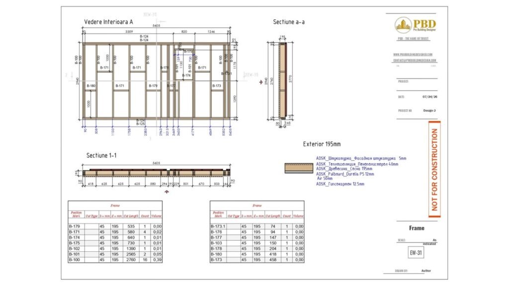
These may include:
- Timber framing layouts
- Wall panel shop drawings
- Floor cassette drawings
- Roof cassette drawings
- Sections
- Details
- Member schedules
- Cut lengths
- Sheathing layouts
- Assembly information
- Fabrication documentation
The workflow might be:
Coordinated Timber BIM
↓
Defined Panels & Cassettes
↓
Framing Development
↓
Shop Drawings
↓
Member / Production Information
↓
Manufacturing
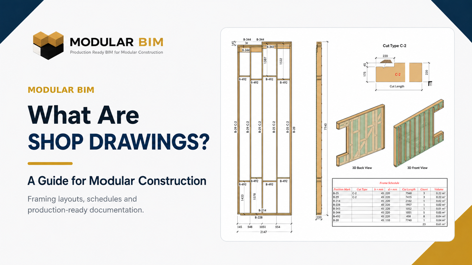
For example, a wall-panel shop drawing might combine:
- Framing elevation
- Overall dimensions
- Member IDs
- Door and window openings
- Section
- Assembly build-up
- Member schedule
A floor cassette drawing may combine:
- Framing plan
- Front or side view
- Sections
- Joist marks
- Member sizes
- Cut lengths
- Schedule
This is more than exporting a screenshot from a BIM model.
The objective is to organize model information into documentation that people can understand and use.
For a deeper explanation of drawing types, fabrication information and production documentation, see our guide to shop drawings for modular construction.
Coordinating Timber Framing with Architecture and MEP
Timber framing does not exist independently from the rest of the building.
Architecture, structure and building services all compete for limited space.
This becomes particularly important in modular and panelized construction, where changes made after manufacturing begins may affect multiple assemblies.
Typical coordination conditions include:
- Door and window openings
- Plumbing penetrations
- Duct routes
- Electrical service zones
- Floor openings
- Roof openings
- Structural beams
- Wall studs
- Headers
- Module boundaries
- Cassette interfaces
Consider a pipe passing through a floor system.
The coordination question is not simply:
Does the pipe intersect a joist?
A proper review may also consider:
- Is the structural opening permitted by the engineering information?
- Is the penetration positioned correctly?
- Does it conflict with another service?
- Is it too close to the cassette boundary?
- Can the service be installed during production?
- Is the opening reflected in the production drawing?
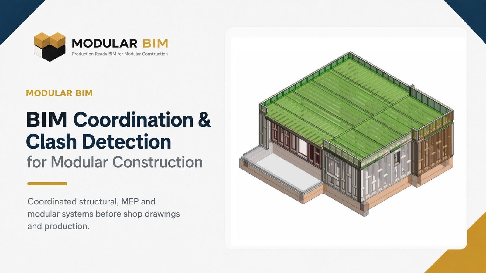
These interfaces are part of a wider BIM coordination and clash detection workflow that should be resolved before detailed fabrication information becomes difficult to revise.
For modular manufacturing, a coordinated framing model should support the next production step rather than merely produce a low clash count.
How Timber Framing BIM Supports DfMA
Timber framing BIM can also support Design for Manufacture and Assembly (DfMA).
DfMA encourages teams to consider manufacturing and assembly while building systems are still being designed and developed.
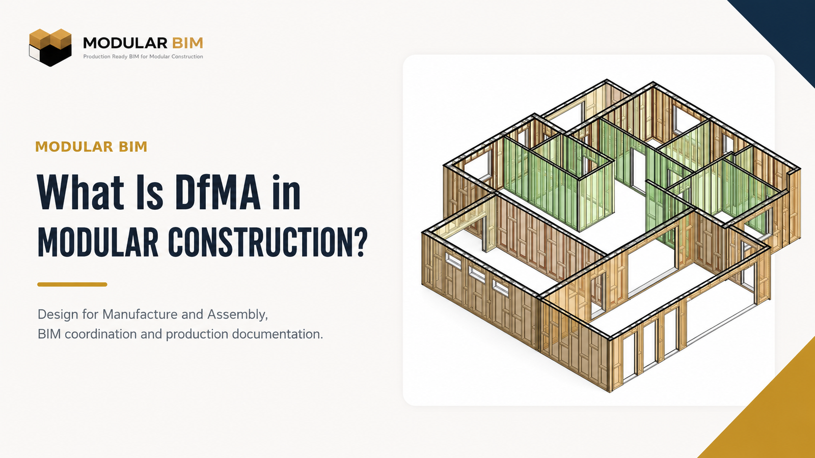
These principles form part of a broader DfMA in modular construction approach, where manufacturing and assembly requirements influence how systems are developed before production.
Timber and panelized systems offer several opportunities for this.
Repeatable Panels
Repeated room layouts or wall conditions may allow the same or similar framing logic to be reused.
BIM can help identify and manage these repetitions.
Standardization
Standardized member sizes, panel widths, framing rules and cassette systems can support more predictable production where they align with engineering and manufacturer requirements.
Manufacturing Constraints
Panel sizes, material lengths, transport conditions and production equipment may influence how assemblies are divided and detailed.
These constraints should be understood before manufacturing-level modeling begins.
Assembly Logic
A panel must not only be manufacturable.
It must also work with:
- Adjacent panels
- Floors
- Roofs
- Structural connections
- MEP services
- Module interfaces
BIM gives project teams a way to review these conditions within the wider building.
Coordinated Production Information
DfMA ultimately depends on information reaching production clearly.
A highly detailed timber model has limited value if the associated shop drawings, schedules and assembly information are inconsistent.
The goal should therefore be:
Design Information → Coordinated Timber BIM → Manufacturable Assemblies → Production Documentation
Example Timber Modular BIM Workflow
A practical timber modular workflow illustrates how these different systems connect.
The project may begin with architectural and structural information.
From there:
1. Complete Structural Framing
Primary walls, floors and roof systems are developed according to the available engineering requirements.
↓
2. Exterior and Interior Wall Panels
Walls are separated into defined assemblies with framing, openings and panel geometry.
↓
3. Parapet and Secondary Panels
Additional wall systems are developed using the same controlled information approach.
↓
4. Floor Cassettes
Joists, perimeter members, openings and associated framing are developed into coordinated floor assemblies.
↓
5. Roof Cassettes
Roof framing is divided into appropriate assemblies and coordinated with walls and supports.
↓
6. Sheathing Layouts
Sheathing information can be developed for individual walls, floors or roofs where required by the project.
↓
7. Sections and Details
Critical build-ups and interfaces are communicated through detailed sections.
↓
8. Member Schedules and Cut Information
Individual framing members can be assigned position marks and organized into schedules containing information such as:
- Member size
- Cut length
- Quantity
- Component ID
↓
9. Fabrication and Production Documentation
The final documentation is structured around the requirements of the project and manufacturer.
You can see similar framing, assembly and documentation workflows across our production-ready modular BIM projects.
This workflow demonstrates an important principle:
A production-ready timber BIM process is not one model or one drawing.
It is a connected information system.
Timber Framing BIM Is About More Than Detailed Geometry
It is easy to judge a timber BIM model by how impressive the 3D framing looks.
But visual complexity is not the real measure of quality.
A model can contain every stud and joist while still having:
- Unresolved openings
- Poor panel logic
- Incorrect interfaces
- Missing production information
- Uncoordinated services
- Inconsistent drawings
- Unusable schedules
The more useful question is:
Does the model contain coordinated information that can support the intended modular production workflow?
For manufacturers, that is what separates detailed BIM from production-oriented BIM.
For teams that need this workflow developed on live projects, explore our timber and modular framing BIM services.
Frequently Asked Questions
What is timber framing BIM?
Timber framing BIM is the development of timber structural systems within a Building Information Modeling environment. It can include individual framing members, wall panels, floor and roof assemblies, openings, sheathing, schedules and production documentation.
How is BIM used in timber construction?
BIM can be used to coordinate timber framing with architecture, engineering and MEP systems; develop wall panels and cassettes; organize member information; and produce detailed shop and production drawings.
What is panelized timber construction?
Panelized timber construction uses prefabricated wall, floor or roof assemblies that are manufactured as defined components before being transported and assembled as part of the building.
What information is included in timber framing shop drawings?
Depending on the project, timber shop drawings may include framing layouts, member identification, dimensions, openings, sections, details, member schedules, cut lengths, sheathing information and assembly data.
What are floor and roof cassettes?
Floor and roof cassettes are framed assemblies developed as defined units. They may contain joists or rafters, perimeter members, openings, sheathing and other coordinated construction information.
How does BIM support timber wall-panel production?
BIM can connect panel geometry with framing, openings, sheathing, dimensions, interfaces and documentation. This helps maintain coordination as the wall moves from building design toward panel-level production information.
How does BIM support DfMA for timber modular construction?
BIM can help implement DfMA principles by coordinating repeatable panels, standardized systems, manufacturing constraints, assembly interfaces and production documentation within a connected digital environment.
Need Timber BIM Support for a Modular Project?
Modular BIM supports modular and panelized construction teams with timber framing BIM, wall-panel development, floor and roof cassettes, BIM coordination, shop drawings and production documentation.
Our focus is developing the information between design intent and modular production.
Explore our modular BIM services or view our production-ready modular BIM projects.
Related Posts